O router, where UART thou?
Since my experience programming a microprocessor in ARM assembly on bare metal last semester, I've become much more interested in lower level software and hardware development. I also just read "Hacking the Xbox" and will be taking a special topics class on reverse engineering and hardware security this fall. Between all of this, I'm feeling inspired enough to try and fit some self-teaching into my free time this Summer. Unfortunately though, this realm is less popular than normal development and software security, and the online tutorial ecosystem is nowhere near as saturated. It seems to be up and coming in popularity though, as hardware hacks have been featured on the front page of Hacker News many times in recent months. I would bet that this isn't a short term trend either. As more everyday things become computerized (the dreaded "internet of things"), I believe hardware security will only become more important.
It took a while to just decide where to start in my quest to become a 1337 hardware hax0r. Many hardware hacks are device specific, but I wanted something simple and general that I could do with (mostly) things I already owned. I happened across this Black Hat talk on UART hacking last semester during a research project, and in it, one of the researchers says that it's so easy that he hardly considers it hardware hacking - the perfect place for a beginner like me to start! These researchers were using a buspirate to access debug shells often left accessible in common electronics by the hardware developers. The buspirate has lots of features and can speak just about every hardware language there is, so I made the heavy thirty-some dollar investment to buy one along with a set of probes. I also decided that any serious hardware enthusiast should own a digital logic analyzer. In my interactions with people who do this type of thing for a living, Saleae was recommended for its decently priced hardware and top of the line software, so I bought their bottom tier model. And no, I wasn't paid to say that (I wish).
Now, armed and dangerous and itching to pick a fight with a circuit board, I needed a target. I happened to have a spare router lying around, so I decided to take it apart. I had also installed OpenWRT on it, so I knew that if I were to post any output I get, nothing would be proprietary and potentially legally unfortunate (to the best of my knowledge, hobbyist hardware tinkering is okay as long as there is no DRM circumvention, but I'd rather be safe than sorry!).
So that's how this project got started! Read on for a tutorial on UART debugging based on my, admittedly brief, experiences.
First of all, what's UART?
UART stands for Universal Asynchronous Receiver/Transmitter. Okay, but what does that mean? It's essentially a standard (universal) piece of circuitry for two-way communication (receiver/transmitter) between peripherals without a shared clock (asynchronous). Less popular is USART, which is very similar but also supports synchronous data transfer. UART is used in many circuits for serial communication, which is the idea of sending information over one wire, one bit at a time. This is useful, because though data is usually processed in parallel circuitry, we often can't afford to have 32 wires between two chips to send an entire 32 bit word at one time. This is expensive in terms of manufacturing costs as well as space used on a board. Using UART, we can cut down two way asynchronous communication of arbitrarily sized data to just a couple wires, with the trade-off being slower communication.
How does UART work?
UART typically has three primary wires, and a fourth auxiliary wire. The first is, of course, ground. Any time two circuits interact, they need to have a shared ground. The other two important wires are called tx and rx, standing for transmitter and receiver lines, respectively. Data is sent out of a UART module on the tx line, and is read into an UART module on the rx line. As a result, when two UART interfaces communicate, the first's tx line will be connected to the second's rx line, and the first's rx line will be hooked up to the second's tx line. That way, all information transmitted by the first will be received by the second, and vice versa. Makes sense, right? The fourth line is Vdd, or the operating voltage of the circuit. I called this one auxiliary because, though the two sides do need to operate at the same voltage, they don't have to operate off of the same source.
Now, because UART is asynchronous, the two communicating modules don't know when the other is sending data. As a result, they need to use a basic code to let each other know when they are sending, and when they are done sending a piece of data. That way the receiving end can properly interpret the serial bits being sent over the wire. The protocol is pretty simple. Before sending a byte of information, send a "start bit". When the receiver gets a start bit, it knows that a piece of data is going to be sent. The receiver then reads the next 8 bits using a preconfigured frequency as they are sent. After the data bits, an optional "parity bit" and finally a "stop bit" are sent so the receiver can do basic error checking and knows that the transmission ended. There are slight variations on this protocol, and both sides must be configured to use the same variation with the same baud rate, or frequency.
Show me!
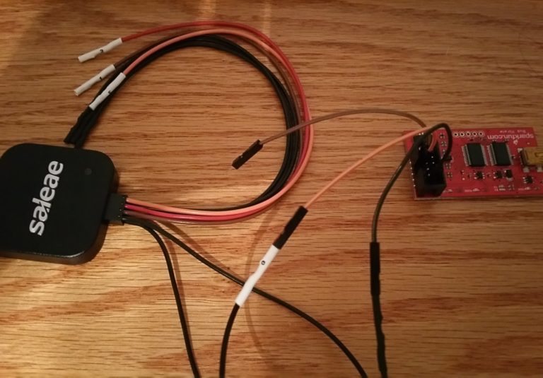
All of this is hard to explain and understand with just words, so lets look at an example using our buspirate and digital logic analyzer. First we'll hook up the tx line of the buspirate to input zero of the logic analyzer and connect the grounds of each.
Next we're going to put the buspirate in UART mode with a baud rate of 115200 bits per second and the default configurations of the basic protocol described above.
HiZ>m
1. HiZ
2. 1-WIRE
3. UART
4. I2C
5. SPI
6. 2WIRE
7. 3WIRE
8. LCD
x. exit(without change)

(1)>3
Set serial port speed: (bps)
1. 300
2. 1200
3. 2400
4. 4800
5. 9600
6. 19200
7. 38400
8. 57600
9. 115200
10. BRG raw value

(1)>9
Data bits and parity:
1. 8, NONE *default
2. 8, EVEN
3. 8, ODD
4. 9, NONE
(1)>
Stop bits:
1. 1 *default
2. 2
(1)>
Receive polarity:
1. Idle 1 *default
2. Idle 0
(1)>
Select output type:
1. Open drain (H=Hi-Z, L=GND)
2. Normal (H=3.3V, L=GND)

(1)>2
Ready
UART>
Here we can see that we selected the following:
- UART as a protocol
- 115200 bps as our speed
- 8 data bits (one byte) per transfer
- No parity bit
- One stop bit
- rx should remain high (1) when idle, and output high is 3.3V.
Cool, lets send a value through the buspirate to the analyzer and look at the bits sent!
UART>"hello uart"
WRITE: "hello uart"
UART>
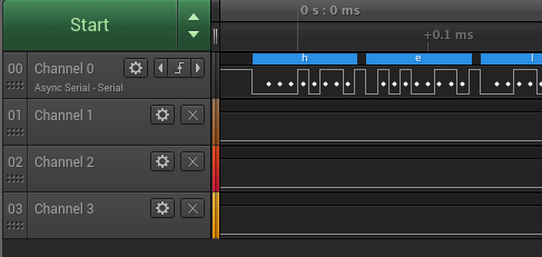
We got it! Here we can see that I set up Saleae to automatically decode what we're sending as the ascii
characters show up above each byte sent. If we look at just the first character, 'h', we see that before any
data is sent, the line stays high. Then it goes low for one period; this is the start bit. The next eight
values are 00010110, which is the ascii representation of 'h' in binary with the least significant bit first.
Finally the line goes high for one period; that is the stop bit. If we look closer at the period of one bit
we'll see that it is approximately 8.833 us. (8.833 x 10^-6)^-1 = 113200, which is within a reasonable
margin of error of our configured baud rate, considering measurement error from the logic analyzer.
Alright! That was more than I planned on writing about UART as a technology. Let's get to the practical stuff now.
Let's access a router!
One of the many common uses of UART these days is to provide a convenient debugging port for electronics that can support a shell. This way, the developer can hook up three wires and have access to a shell that allows them to test changes they've made. The security interest here is that a lot of the time, this UART debug shell is left completely open in the release version of the product, meaning that those of us who know what to look for can get a level of access to our devices we might not otherwise get!
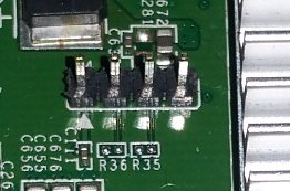
Not all electronics support this, but those that do usually have their UART pins nicely organized in a small group of four pins right next to each other. They may have actual pins soldered on, or they might just be open ports on the board.
Here's an example on a router that has the pins.
And here's a picture of the one we will be accessing. This one didn't ship with pins soldered on, but that's okay.
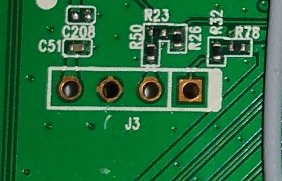
As of right now, all we have is a suspicion that these ports are hooked up to the main chips UART and we're hoping that this will give us some meaningful access to the device. To test these hypotheses, we need to do some analysis. We'll start with the most basic of measurements using a digital multimeter. We're primarily looking for ground and power pins. Before actually using the multimeter we can make some educated guesses just by looking at the pins and the board around them. Looking at the picture above, the second port from the left appears to have 4 leads coming out of it in a cross formation. This is normally indicative of a ground pin. The port on the far left has a slightly wider lead coming out of it than the others. Power lines are normally slightly wider so a good guess would be that this is the power pin. To more rigorously find ground and power we can hookup one multimeter probe to the ground lead on the power supply to the router, and test the pins using the other probe.
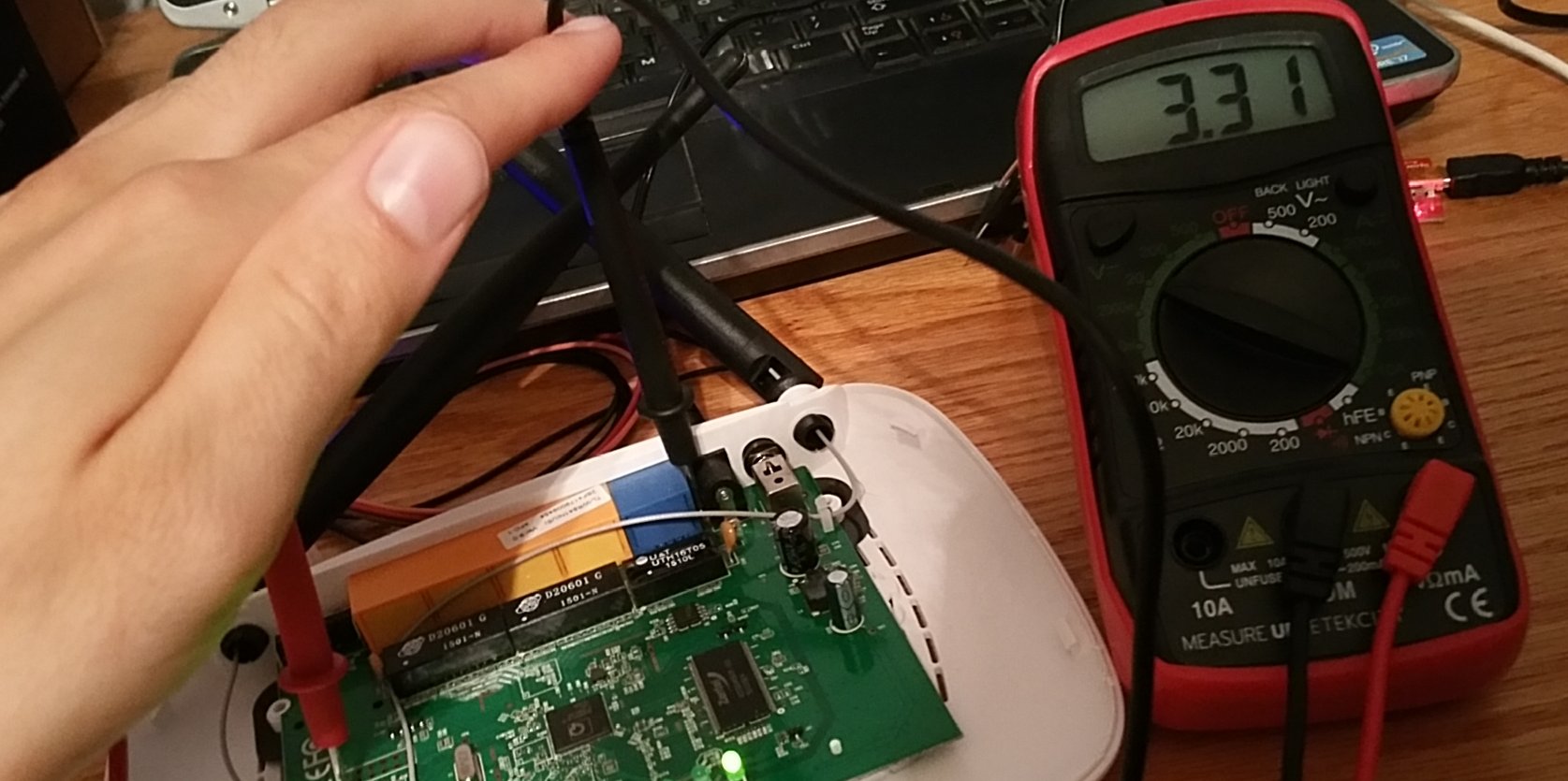
(I think the hardest part of this entire post was taking a picture of myself holding both probes of the DMM with one hand).
Sure enough, our measurements verified our guesses!
Of the two remaining pins, we know one of them is tx and one is rx. In order to figure out which is which, we'll hookup our logic analyzer to both. Just connecting the analyzer isn't enough though, we want to be analyzing when the chip is transmitting data. We don't know anything really about this specific set up, but a good starting point is listening right as the chip gets power. Hopefully, we will get some boot output, or at least some type of signals that get sent out when the chip first starts up.
Here's what we get on from the logic analyzer when the inputs are set to trigger on a rising edge and then we power cycle the router.
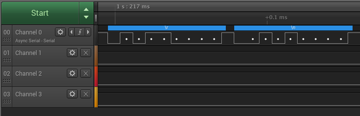
Cool! A couple seconds after the trigger we see some solid output on channel 0, which happens to be the far right port on the board. And by using the autobaud detection feature in the DLA software we find out the baud rate is approximately 121212 bps. (This could also be gathered using the simple period -> frequency calculation done above). This is a non standard baud rate, but that's okay. Also notice that, just like in our practice with UART, this output is high when idle, has one stop and start bit, and has no parity bit. Now we're ready to hook up the buspirate! Remember, we hook up the buspirate's rx to the router's tx, which we just determined to be the far right port, and the router's rx, which must be the only remaining port, to the buspirate's tx.
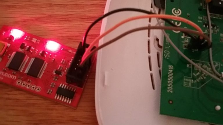
Now we set up our buspirate for communicating with UART as a two way bridge so that we can send and receive information from the UART on the router. Note that we had to dive little deeper into the buspirate's menus to get the correct baud rate. I used a table found here to get the correct magic number. Only the differences from the above configuration are noted here.
...select UART mode...

Set serial port speed: (bps)
1. 300
2. 1200
3. 2400
4. 4800
5. 9600
6. 19200
7. 38400
8. 57600
9. 115200
10. BRG raw value

(1)>10
Raw value for BRG (MIDI=127)

(34)>32

...select other UART options...

UART>(0)
0.Macro menu
1.Transparent bridge
2.Live monitor
3.Bridge with flow control
4.Auto Baud Detection
UART>(1)
UART bridge
Reset to exit
Are you sure? y
Now we power cycle the router and watch the boot output pour across the screen!
U-Boot 1.1.4 (Build from LSDK-9.5.3.16 at Jan 6 2015 - 17:40:06)

ap143 - Honey Bee 1.1

DRAM: 32 MB
Flash Manuf Id 0xc2, DeviceId0 0x20, DeviceId1 0x16
Flash: 4 MB
Using default environment

...lots more bootloader output...

Autobooting in 1 seconds
## Booting image at 9f020000 ...
Uncompressing Kernel Image ... OK

Starting kernel ...

[ 0.000000] Linux version 3.18.20 (buildbot@builder1) (gcc version 4.8.3 (OpenWrt/Linaro GCC 4.8-2014.04 r46450) ) #1 Fri Sep 4 21:55:57 CEST 2015
[ 0.0] bootconsole [early0] enabled

...lots more kernel boot output...

[ 0.630000] Serial: 8250/16550 driver, 16 ports, IRQ sharing enabled
�[ 0.660000] serial8250.0: ttyS0 at MMIO 0x18020000 (irq = 11, base_baud = 1562500) is a 16550A
�@@@@pNvwpppp껽@�������@û����p�@�������
����@@@@pNvwpppp�@�������@û����p�@�������
Wait a minute. Everything looks normal until we get to the lines at the bottom. Then it turns into random junk. This looks to me like the baud rate changes part way through the boot process. After a little bit more tinkering along the same lines of everything above, I found out that the baud rate does in fact change to 115200 at this point in the boot process. Taking this into account, we can get the rest of the output. Most importantly, we get this.
Press the [f] key and hit [enter] to enter failsafe mode
Press the [1], [2], [3] or [4] key and hit [enter] to select the debug level
Please press Enter to activate this console.
Wait for the boot process to finish, press enter, and...
root@OpenWrt:/#
We have a shell! Root level access, no password required. From here, we can modify files and programs that are running. People have even found gems like private encryption keys on devices like this. There is also a lot of interesting and useful information in the boot output that I didn't include here. We won't get into this analysis though, as we've already gone through what UART is all the way to a simple but practical application of it in the field of hardware security.
My next goal is to get a ROM dump of the router using SPI, so hopefully we'll have a post about that in the future. Please leave feedback in the comments!